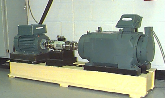
As shown in Figure 1 above, the test stand consists of a 2 hp motor (left), a torque transducer/encoder (center), a dynamometer (right), and control electronics (not shown). The test bearings support the motor shaft. Single point faults were introduced to the test bearings using electro-discharge machining with fault diameters of 7 mils, 14 mils, 21 mils, 28 mils, and 40 mils (1 mil=0.001 inches). See FAULT SPECIFICATIONS for fault depths. SKF bearings were used for the 7, 14 and 21 mils diameter faults, and NTN equivalent bearings were used for the 28 mil and 40 mil faults. Drive end and fan end bearing specifications, including bearing geometry and defect frequencies are listed in the BEARING SPECIFICATIONS.
Vibration data was collected using accelerometers, which were attached to the housing with magnetic bases. Accelerometers were placed at the 12 o’clock position at both the drive end and fan end of the motor housing. During some experiments, an accelerometer was attached to the motor supporting base plate as well. Vibration signals were collected using a 16 channel DAT recorder, and were post processed in a Matlab environment. All data files are in Matlab (*.mat) format. Digital data was collected at 12,000 samples per second, and data was also collected at 48,000 samples per second for drive end bearing faults. Speed and horsepower data were collected using the torque transducer/encoder and were recorded by hand.
Outer raceway faults are stationary faults, therefore placement of the fault relative to the load zone of the bearing has a direct impact on the vibration response of the motor/bearing system. In order to quantify this effect, experiments were conducted for both fan and drive end bearings with outer raceway faults located at 3 o’clock (directly in the load zone), at 6 o’clock (orthogonal to the load zone), and at 12 o’clock